MathWorks
MATLAB and Simulink integrate into the High-Level Synthesis (HLS) design flow to enable a seamless algorithm-to-RTL process with continuous verification. The workflow begins with algorithm development in MATLAB or Simulink, where floating-point models are created and validated. These models are then translated into C++ for High-Level Synthesis.
Crucially, the C++ models generated for HLS are folded back into the original MATLAB or Simulink testbenches, enabling system-level verification against the algorithmic reference. As the C++ model is refined for synthesis, it remains testable within the MathWorks environment using the High-Level Verification (HLV) framework. HLV provides model instrumentation and coverage analysis directly within the MATLAB testbench, helping improve DUT quality and the effectiveness of stimuli for subsequent RTL verification.
This integrated approach connects algorithm development, High-Level Synthesis, and RTL verification into a unified flow, ensuring consistent validation from model to implementation.
-
High-Level Synthesis Flow from MATLAB/Simulink Model
High-Level Synthesis Flow from MATLAB/Simulink Model
Introduction
When MATLAB and Simulink became the de-facto standard in algorithm development, many research teams started to look at possibilities of generating RTL directly from MATLAB code, especially for FPGA design. Many of those solutions were targeted to certain applications or technologies. The approach is promising but it has a huge abstraction level chasm between the expressively powerful and dynamic MATLAB or Simulink model against the static and bit-level Verilog or VHDL. These generators require a modeling style that limits the freedom of algorithm developers to use the full power of the MATLAB language or Simulink models.
High-Level Synthesis opened new possibilities to model and develop HW at a much higher abstraction level using C++ or SystemC as modelling language. The MATLAB-HLS-RTL flow introduces a new intermediate language, but it allows each language to be used in its optimal abstraction level. This reduces the verification complexity and bridges the abstraction level chasm between MATLAB and RTL. Algorithm developers can use MATLAB as they are used to, which maintains their productivity. The abstraction level difference between MATLAB and C++ is small and HLS enables architecture exploration without changing the source code. HLS-to-RTL synthesis is a reliable technology today.
Model translation from MATLAB to C++ or SystemC has been available for a long time. Yet, the code generation has been targeted and optimized for simulation and embedded software, which is not necessarily optimal for supporting HLS. Editing the generated C++ code manually breaks the validation flow. HLS tools need different coding styles, which limits a fully automated flow to a specific HLS tool. Furthermore, translating the dynamic MATLAB features and operator-based complex operations to HLS optimized C++ requires a certain level of synthesis. Therefore, the manual translation of MATLAB or Simulink model to HLS C++ code is still one of the best methods.
Limitations of the existing design processes
There are several problems to be solved before an abstract MATLAB algorithm model is converted to an efficient HW implementation. The main issue is the structural difference between abstract, sequential simulation code with operator-based vector and matrix operations in MATLAB and HW architecture with parallel processing and distributed memory architectures. A widely used method is to write the MATLAB code in a very low level – almost RTL – that makes the translation easy but slows down the simulation dramatically and limits the freedom of algorithm developer. Replacing the MATLAB vector and matrix operations with C++ linear algebra library functions is not possible, because their coding style is optimized for software execution and is not synthesizable with HLS tools.
Another problem is the required block-level architecture in HW. MATLAB code may have function hierarchy or System Object -based class hierarchy, but it doesn’t define parallelism nor the block hierarchy of the HW. Most MATLAB designs use multiple toolbox functions or complex operations like matrix multiplication that may have to be handled as individual modules in the HW. Furthermore, MATLAB language doesn’t have any communication channel like ac_channel that is needed to define the communication between two concurrent clocked modules in HW. In Simulink the design can be partitioned graphically using subsystems communicating with each other through channels. This model hierarchy can be translated directly into HW architecture.
Reusability of the translated models and tool dependency are also significant problems. If the models are just translated and not optimized for parameterization nor templatized for feature configurability, reusing the models from previous projects may be difficult. An earlier version of the methodology introduced in this paper had a reusability problem too. Automatically generated models are typically not reusable.
From MATLAB/Simulink to HLS Design Methodology
MATLAB and Simulink models can describe any algorithm, and they can be built in very different ways. MATLAB model can be anything between a single MATLAB script and hierarchical object-oriented design. Simulink models can also be constructed by using only library primitives, which is not a very efficient methodology for large designs, or by using custom MATLAB functions or System Objects and parameterizable subsystems. That makes automated design translation very difficult and requires different methods in the manual translation process too.
The MATLAB/Simulink-to-HLS design methodology has multiple phases and bi-directional communication. The translated models, regardless of if manually or automatically, must be validated against the original higher abstraction level model to ensure that the functionality is correctly translated. A proper functional validation requires a test coverage close to 100%. Otherwise, some features or corner cases may not be tested. Figure 1. shows the multiple steps and validation paths of the design process. This design methodology covers both MATLAB and Simulink designs and MATLAB functions or system objects in a Simulink block diagram.

Figure 1. MATLAB/Simulink-to-HLS design flow The process begins with a manual or semi-automatic model translation. The five translation options introduced in this paper describe the handling of the different model types. Using a HLS model library makes the translation of matrix and vector operations easier. Later, the validation steps are needed to ensure the correctness of the translated model and algorithmic performance of the bit-accurate implementation.
Usually, to reach the optimal HW architecture, the design must be optimized for HLS, which requires structural changes to the code, like re-partitioning function call trees, adding data buffers and sometimes even re-coding some parts of the algorithm. Therefore, a coverage analysis is required to ensure that the code modifications do not break the algorithm in any use case. Once the model is thoroughly validated and verified, it can be synthesized to RTL and verified using the standard RTL verification methodologies like UVM.
Several translation projects have proven that MATLAB and Simulink models should be maintained with double precision numbers, which is the MATLAB default data type. Using a fixed-point representation increases the number of lines of code and adds fixed-point specific functions, making it more difficult to translate and especially difficult to validate. In double precision model a deviation of 10-15 between MATLAB and C++ models is normal background noise caused by order of operation differences and floating-point mantissa size. A significant difference is 10-3 to 10-6 depending on the design and fixed-point word length used. Yet, the acceptable difference between the double precision and fixed-point implementation depends on the algorithmic performance requirements for the overall system.
Analyzing block-level architecture
First, the MATLAB design must be analyzed for computational resource needs and data transfers between the functions. Based on this information, the HW architecture can be sketched.
The computational resource needs of a code segment or function can be analyzed by using MATLAB’s profiler, manual estimation, or simply by measuring the simulation time of the part of the algorithm in relation to the total simulation time. This estimate is not accurate, but it gives an indication of which parts of the simulation model may need increased parallelism, and possibly multiple parallel instances of a certain block.
Data transfer rate is an even more important metric. In the HW the data must be stored in a memory or streamed through the signal path. If a module interface has a large data set like a high-resolution image, a ping-pong memory interface requires a RAM that is twice as big as the dataset itself. Optimizing the data sizes by defining the module structure in a MATLAB model saves time and effort later in the translation.
Model analysis in Simulink is easier, because the design is already modular, and Simulink has several helpful features to analyze the design. In many cases the HW block-level architecture can be extracted from the Simulink subsystem hierarchy, as demonstrated in Figure 2. In a deep hierarchy all workspace parameters that should be configurable in the HW implementation must be brought up to the top-level interface.
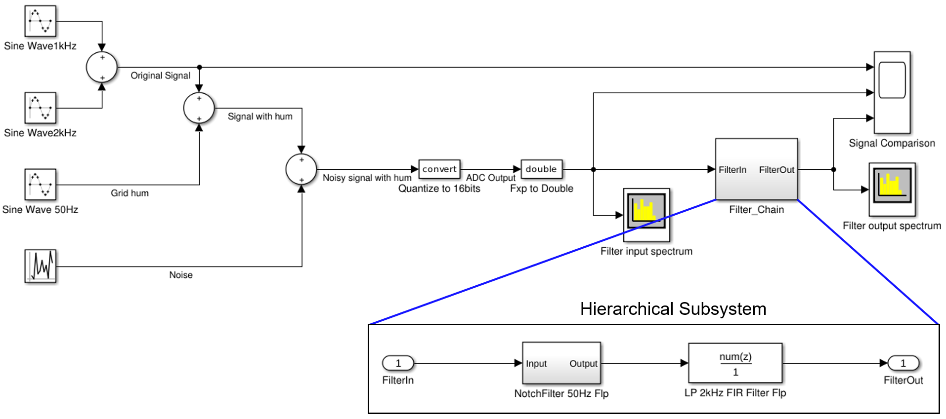
Figure 2. Extracting block hierarchy from Simulink model. Translating MATLAB scalar code to HLS C++
Translation of a MATLAB scalar model is mainly a syntax conversion from MATLAB to C++. Some details must be added manually, like variable declarations that are needed in MATLAB only in special cases or declaration and initialization of static variables. Loop syntax and array indexing are typical sources of errors. In MATLAB array indexing begins with 1 and in C++ with 0. These types of coding errors can be found with a HLS linting tool.
Data type definitions should be made in a separate type definition file. This enables using a floating-point type ac_ieee_float64 in the conversion phase.Alternatively, a very long fixed-point data type with 64 or 128 bits can be used. When the functionality is validated, the C++ model can be quantized, and data types changed to the final fixed-point types.
Arbitrary length fixed-point data types are needed in HLS. Two fixed-point data types are available as open source under Apache 2.0 license: Algorithmic C fixed-point library (ac_fixed.h) and SystemC fixed-point data types. SystemC data types are slower to simulate and clumsier to use than ac_fixed-types, but functionally both data types are almost identical.
In the class-based example shown in Figure 3. the data types in_t, accu_t and out_t are defined in the class template, which makes the model more configurable and independent of the global type names. Furthermore, the shift register vector SReg is declared as a private data member of the class.
The C++ function interface is using an ac_channel type that enables using the model as a concurrent clocked process with register or FIFO interface in HW. Using the ac_channel requires a data availability test in the C++ code to avoid simulation problems. The if-statement is replaced by a corresponding handshaking signaling in the HW as well as the read-operation. The local accumulator variables that are only initialized in the MATLAB model, must be declared in the C++ code as well.
The functional code inside the for-loop needs only a syntax conversion from MATLAB to C++. The output needs a write-operation in C++ if the ac_channel interface is used. With a standard C++ function interface, assignment to the output variable is enough.
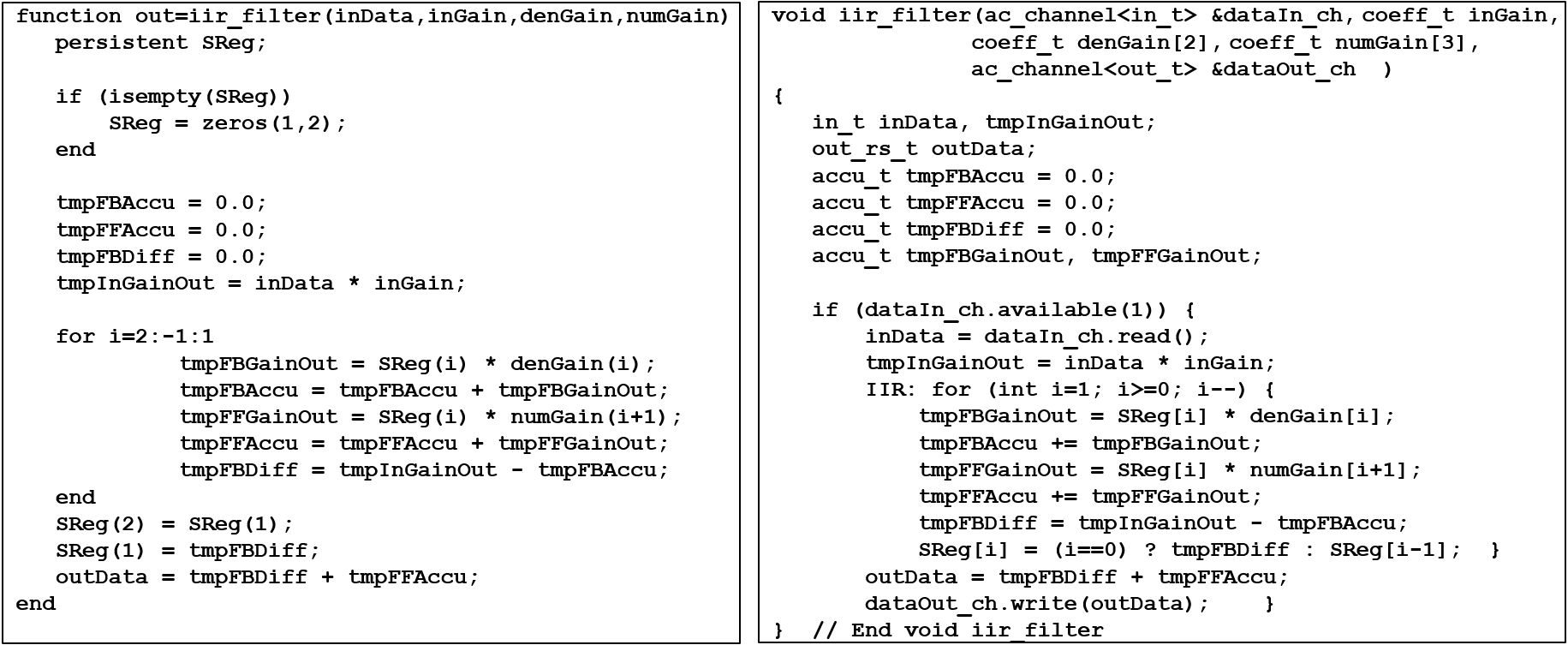
Figure 3. MATLAB Scalar code translated to C++ Translating MATLAB matrix or vector model to HLS C++
Operator-based matrix and vector operations are more complicated. In MATLAB a statement A = X * Y’ is just one line MATLAB code, but the matrix multiplier implementation in C++ is a large function. Many helpful function libraries can be found in hlslibs.org [12], e.g., ac_math and ac_dsp and matrix library that has C++ function equivalents to most MATLAB operator-based matrix and vector operations.
In MATLAB the user can write multiple matrix and vector operations in a single statement. Because the C++ implementations are functions, there can be only one function call in each statement. Longer statements must be split into multiple single operation statements. As a free add-on, MATLAB indicates the size of the intermediate array variables, that can be used to declare the array sizes in C++, as a side effect. Translation of a simple MATLAB matrix operation is shown in Figure 4.
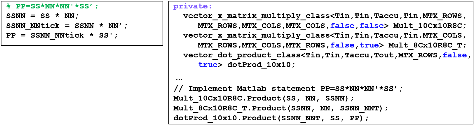
Figure 4. Translation of MATLAB Matrix code to C++ using HLS matrix library Translating Simulink design hierarchy to HLS C++
The properly assembled Simulink model has a useful design hierarchy that can be transferred into the HLS model as is. Most HLS tools do not accept any functional operations in the block hierarchy level, so the design must be “cleaned up”. The hierarchy should be kept as simple as possible to enable exploration of different HW implementations.
The module architecture can be implemented as a C++ function or class hierarchy, or an SC_MODULE hierarchy in SystemC. The hierarchical blocks may contain both functional blocks and further hierarchical blocks. Figure 5. demonstrates how a block hierarchy of the DUT can be extracted from the Simulink model having different block implementations. The hierarchical subsystem becomes a hierarchical block in the HLS model and the functional subsystems are translated to functional blocks.
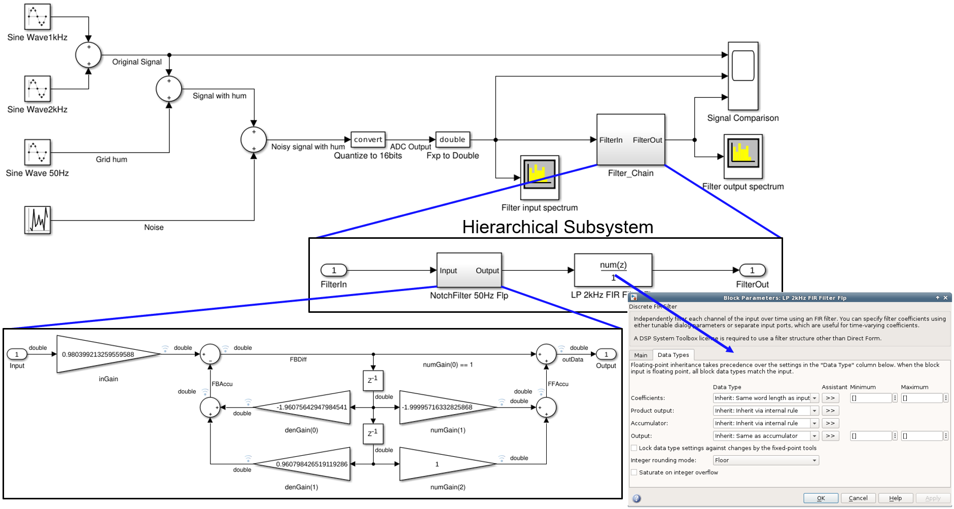
Figure 5. Simulink model hierarchy Translation of a functional model depends on the model implementation in Simulink. If the Simulink model uses MATLAB function blocks or System Objects, MATLAB model translation can be used. Library component based schematic implementations in Simulink need a different approach.
Translating Simulink leaf-level block diagram to HLS C++
The leaf-level block diagram using primitive library elements, also called a Simulink schematic, is more difficult to translate. Figure 6. demonstrates a typical Simulink schematic implementation.
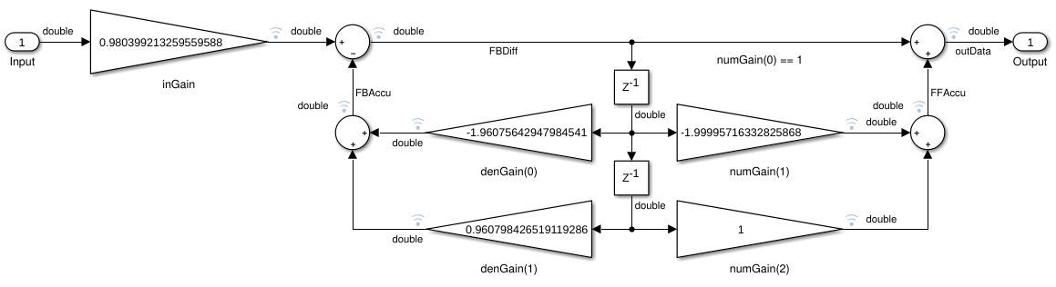
Figure 6. Simulink block diagram with primitive library elements This example is not difficult to translate to C++. The model has five multiplication operations, four additions and two registers. It can be written as a for-loop that simplifies the structure, or it can be flattened. The translation begins from the second register. The output of both multipliers are stored into a local variable. When the multiply-accumulate operations are computed, the register gets the value of the first register.
Now the multiplications connected to the first register can be calculated and summed up with the results of the previous stage. The result of the input multiplication can be added to the sum of the feedback path and assigned to the first register. The output is the sum of the first register input and the sum of the feed forward path. An example implementation with a for-loop is shown in figure 7.
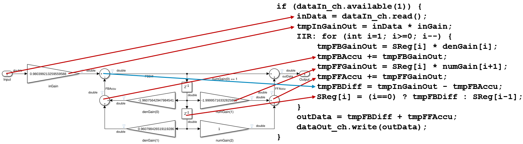
Figure 7. Translating Simulink schematic with primitive elements to C++ Simulink library blocks can be more complicated to translate. They can be filters, FFTs, matrix operations, memories, or other complex mathematical functions. Open-source HLS function libraries can be used to implement Simulink library blocks in the same way as toolbox functions in MATLAB.
Validation and verification flow
Multi-language design flows must have a seamless verification and validation process to ensure the design integrity throughout the process. Using C++ as an intermediate language in the design flow increases the number of verification steps, but it provides a comprehensive set of tools that make the verification easier.
This design flow has three validation and verification steps as shown in Figure 1:
- Functional validation of the hand-written C++ code against the original MATLAB model with MATLAB testbench.
- Validation of the algorithmic performance of the quantized C++ model in the MATLAB testbench
- Coverage analysis of the C++ model in MATLAB testbench
Verification of the synthesized RTL code against the C++ model is a standard part of the Catapult framework.
Validation of the hand-written C++ model against the MATLAB model is the most critical phase. It is implemented by using the MATLAB mex external C API. The C++ model is automatically wrapped into a mex wrapper and compiled to a shared object and an S-function block for Simulink is generated in some HLS tool frameworks. The shared object is instantiated into the MATLAB or Simulink testbench manually, parallel to the original MATLAB reference model. Functional difference of the C++ model output should be in the range of +/-10-15 compared the output of the MATLAB reference model.
The same testbench can be used for the performance analysis of the fixed-point HLS model with minor changes to the scoreboard. For MATLAB testbench no modifications are needed, but in Simulink the input and output data types must be matched to the corresponding data types in the HLS model. Figure 8. shows the instantiation of the HLS DUT into the Simulink testbench. Some additional analysis components are needed to measure the difference between the Simulink and HLS model outputs.
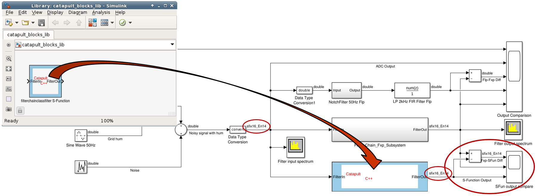
Figure 8. Instantiating HLS DUT into Simulink testbench Coverage Analysis for the C++ model provides information about the test quality. C-level code coverage tools instrument the DUT with probes that store line, decision, and expression coverage information during the simulation and stores the information into a coverage database. The instrumented C++ model can be wrapped into a mex wrapper, instantiated into MATLAB testbench, and simulated in MATLAB. The coverage information gives feedback that helps the test engineer to improve the MATLAB test setup to cover all corner cases. The same test scenarios can be reused later in UVM environment as stimulus.
C-level verification reduces the verification time dramatically, with up to 1000 times faster execution. This allows running more functional tests, resulting in better design quality. A comprehensive study by University of Oulu reports that their C-level simulations ran 191 times faster than equivalent RTL simulations in a UVM environment.
Verification of the generated RTL code is a standard procedure in most HLS tools. The most common verification method is RTL co-simulation, which simulates both the generated RTL code and the HLS C++ code in parallel and compares their output. If the results are equal, the synthesis was correct, and the hardware works as specified. In addition to the RTL co-simulation, there are formal methods available. The same RTL co-simulation setup can be reused in a UVM environment.
Quantization of translated HLS
Validation of the translated model is done with floating-point or very wide fixed-point data types to keep the focus of the validation on the functionality, without introducing quantization effects. When the model functionality is completely validated against the original MATLAB or Simulink model, it can be optimized for HLS. The optimization has two major parts: structural optimization covering module and loop optimizations and fixed-point optimization a.k.a quantization.
During the quantization process, all variables in the HLS model are analyzed and declared to optimal length fixed-point or integer data types that are synthesized to RTL bit vectors of the same length as the C++ variables. Quantization process has been a subject of many studies and there are very comprehensive Signal-to-Noise-Ratio (SNR) -based methodologies that analyze the effects of quantization noise in the system context, but usually the effort is far too high compared to the benefit. A simpler methodology may require more simulation cycles, but the results are comparable to the SNR-based quantization results.
Value Range Analysis (VRA) -based quantization methodology is a simple methodology to find an optimal fixed-point data type for each variable in the design. VRA is simulation-based methodology that analyzes the propagation of the limited accuracy of input values through the step sizes of the internal variables and recommends word lengths that can represent the minimum step size. In this methodology, the input signals must be “pseudo quantized” having a limited number of possible values. VRA requires an instrumented data type, e.g., ac_fixed<>, that collects and stores maximum and minimum values, signedness, minimum non-zero absolute value, and minimum non-zero absolute difference between two consecutive samples during the simulation. These values are used to calculate the required number of integer and fractional bits:
int_bits = ceil(log2(maxval)) + signed;
frac_bits1 = -floor(log2(minval));
frac_bits2 = -floor(log2(mindiff));
The number of integer bits contains the sign bit, and it can be used as it is. The minimum absolute value is not necessarily the smallest value the variable must be able to represent. For example, a sine wave has a relatively large step size around zero, but a small step size around the pinnacle. To get a better estimate of the required number of fractional bits, both the minimum absolute difference and the minimum non-zero absolute value are needed and the bigger of the two fractional bit numbers should be used. A type declaration of ac_fixed using these numbers looks like:
typedef ac_fixed<(int_bits+frac_bits2), int_bits, signed> fixed_t;With SystemC fixed-point data types, the signedness defines, if sc_sfixed<> or sc_ufixed<> type must be used. Otherwise, the type definition is the same.
When Value Range Analysis feature is activated, it collects the variable values during the SystemC simulation and stores the results into a file that can be analyzed in the spreadsheet tool or a Design Analyzer supporting Value Range Analysis perspective. Figure 9. shows part of the initial simulation results for the IIR filter block. All internal variable types are defined as 64-bit fixed-point with 32 integer bits. Only the input and output variables are declared as 16-bit variables based on the specification.
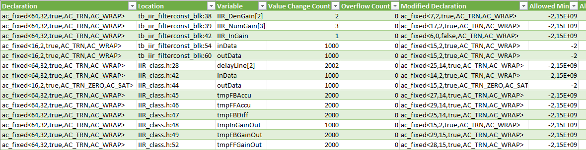
Figure 9. Catapult fixed-point analysis results for the IIR filter block This table contains all information collected during the simulation. In addition to the presented columns, there are columns displaying the measured minimum and maximum values and other relevant information that can be used for further analysis. The modified declaration column contains the recommended data types for each variable. For the arrays, the worst-case values are used.
The VRE results may need some fine tuning based on the performance analysis simulation with MATLAB. Like all simulation-based analysis, the VRE results are as good as the stimulus used for the analysis. It should cover the whole value range of the inputs and be long enough to generate enough value changes to each variable. Otherwise, the statistical significance of the measured results may not be enough to create reliable fixed-point type recommendations.
Conclusions
HLS-based MATLAB-to-RTL design process is a good alternative to direct synthesis. Using C++ or SystemC as an intermediate language between MATLAB and RTL moves the HW specific design from MATLAB-level to C++ level, giving algorithm developers freedom to use the full power of MATLAB language. Model translation from MATLAB to C++ takes place in the same abstraction level making the validation and debugging of the translated model easy. A strong validation methodology that reuses the MATLAB testbench, combined with coverage analysis, ensures the functional correctness of the HLS model.
HW related modifications are made to the C++ model only. The C++ model is quantized and optimized for High-Level Synthesis without any modifications to the MATLAB model. The validation environment developed during the model translation phase provides a powerful regression environment that can be used to ensure the model correctness after every modification. HLS tools are usually well connected to RTL verification. Therefore, the verification in this methodology is focusing on the MATLAB-C++ level.
Translating MATLAB or Simulink model to an efficient RTL model is not fully automated yet. The manual conversion process is fast and easy when the HLS optimized library elements are available. The open-source library development enables translating more complex MATLAB models in a short time.
The design methodology described in this paper has been used in many different types of projects. It has proven to be flexible, easy to deploy, and efficient methodology for all kinds of HW designs. Manual language translation requires some knowledge about the coding style requirements of the HLS tool being used, but by using class-based C++ with templates or SystemC, many of the coding rules can be integrated into the templates.